
High performance electronic fishing device for professionals.
User manual (LH version)
"RICH P-2000" is a professional electronic fishing device new generation, intended for industrial
catching of all types of fish in private reservoirs with fresh water. It works on the principle of
weekend synthesis pulse width modulation (PWM). This technology provided this model with
numerous advantages over the old conventional devices, where such possibilities are not available
due to using outdated schemes.
The main differences of the new model are the smooth adjustment of the output amplitude.
pulses in the entire voltage range with a step of only 2 Volts and the presence of many different
output waveforms. Now the opportunity has arisen full-fledged fishing at any frequency with a
power of only 10 watts and at amplitudes of impulses from 50 Volts. Our dear fishermen have been
waiting for this for a long time, who will now be able, without any fear, to catch stocks of reared
valuable fish species for further breeding.
The use of new technical solutions made it possible to introduce the technology HI-WIDTH.
This is catching fish with wide impulses, which greatly simplified and improved the setting of the
device. By adjusting only one amplitude, the device easily customizable and fully compatible in any
body of water with sensitivity and the state of fish receptors, water conductivity and electrode area.
Clear, soft and confident fish output is a confirmation of this.
The device is easily updated to change existing ones and add new ones.
parameters and fishing modes.
We constantly conduct research and testing to ensure we have the very latest data and
implement new advances.
We hope that fish farming and fishing with our device will bring you pleasure and
satisfaction!

Device characteristics.
Power supply voltage . . . . . 10 - 13 volts (car battery or 12 volt power battery)
Adjustment range of output pulse parameters:
- Frequency (F) . . . . . . . . . . . . . . . . . . . . . . 1 - 80 Hz
- Amplitude (U) ... ... ... .... ... 50 to 320 volts
- duration (L) . . . . . 4.0 - 12.0 ms (milliseconds).
- output pulse shapes . . . . . . . . . 21 shapes
Output power level range. ... ... ... ... ... ... ... ... ... ..... ... . ... ... ... ... ... ... ... ... ... ... ... 7 - 450 watts
Average working power output. ... ... ... ... ... ... ... ... ... ... ... ... ... ... .... ... ... ... ... ... .50 - 180 watts
Consumption current from the battery. ... ... ... ... ... ... ... .. ... ... ... ... ... ... ... ... ... ...1 - 40 amperes
The depth of effective action:
- in normal mode . . . . . . . .. . . .up to 2.5 m . . . .
- in a catfish mode .... ... ... ... ... up to 20 m or more (rivers only)
The radius of effective action:
- in normal mode . . . . . . . up to 7 m
- in a catfish mode ... ... ... up to 50 m
Range of electrical resistance of the water . . . . . . . 29 to 300 ohms.
Catfish mode . . . . . . Yes
Modes of reduction and modulation . . . . . YES
Protection against reverse polarity ... ... ... .YES
Protection against overloading . . . . . . . . YES 2 pieces.
Instrument menu language ... ... ... ... ... ... EN (English) / RU (Russian)
Sound and light indication of output pulses …...... YES
Energy independent memory of set parameters. ... ... ... ... ... ... ... ... ... ... ... 4 pages
Two operating modes: LOW for general users and PRO for advanced users.
Weight of the device. ... ... ... ... ... ... . ... ... ... ... ... ... ... ... ... ... ... ... ... ..up to 1.7 kg
Completeness of the device.
The set of the device includes:
- electronic device "RICH - P-2000";
- control cable with "START" button;
- output cable "MINUS" with a metal braid at the end;
- this user manual.
For fishing, you must additionally have:
- Any 12 - Volt car battery to power the device;
- fishing landing net with a metal ring and an insulated handle;
- several meters of insulated copper wire with a cross-section of 1 mm² for
connecting the landing net ring to the device.
- a boat to move around the reservoir, since fishing from the shore is ineffective. On the
in shallow water, you can use high rubber boots or a wetsuit.
If you plan to use a non-standard car battery, then it must have an output voltage strictly in the
range of 10.2 - 13 Volts and provide
required load current, which is approximately calculated at the rate of 1 Ampere per
every 10 watts of power output. For example, 10 Amperes = 100 Watt
The landing net ring can be made of any metal, except aluminum, which is in water quickly
oxidizes. A ring of wire, rod or tube with a diameter of 4 mm and more is suitable above. For
normal current return in water, the diameter of the ring must be at least 30 cm.
Try to make the landing net light and mechanically strong so that it is easy and work
comfortably and play out large fish without any problems.
It is recommended to connect the wire to the landing net ring using the soldering method,
when using a suitable flux if necessary. Screw connections and conventional wrap wires will
quickly oxidize in water, resulting in a loss of fishing efficiency.
Connection and control bodies
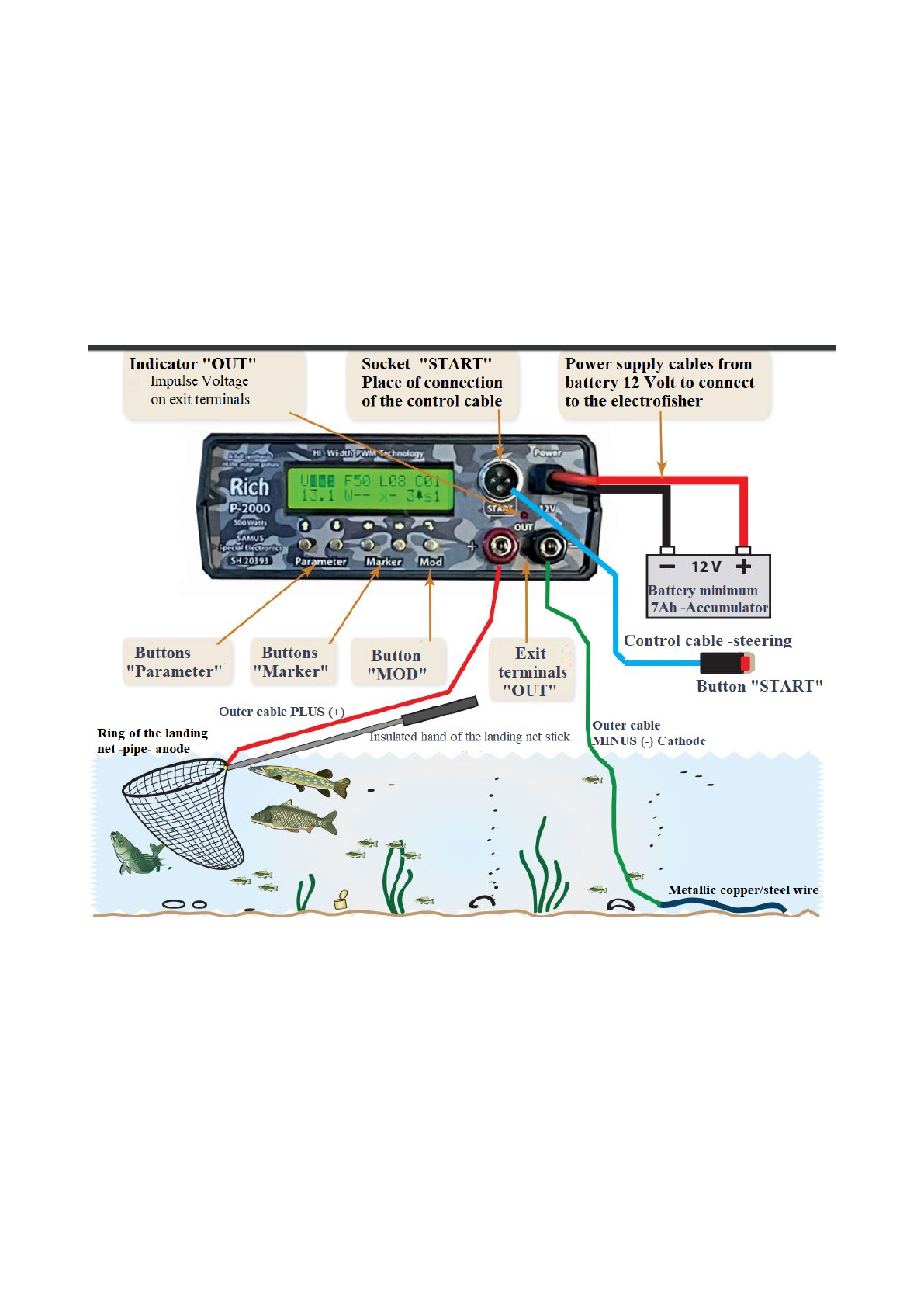
The external view of the device, controls and connection are shown in Fig. 1.
Fig 1. External view of the device
Attention! Before connecting the device for the first time, you must completely familiarize
yourself with the contents of this manual, especially the section “Measures-precautions "
The device is connected according to the above figure.
The “START” jack is used to insert the control cable plug, at the other end of which, under
with a silicone waterproof cap there is a "START" button, with the help of which the device is
turned on / off. It can be screwed onto the landing net handle, but it is better to hold it in your free
hand while fishing. This will make the landing net easier to throw left and right and, especially, take
them fish from under the side of the boat.
The load is connected to the “OUT” terminals. To the red “+” terminal using the connecting
wire connects the landing ring. To the black terminal “-” - output minus cable with metal braid at
the end. It is released into the water behind the boat at the entire length so that the distance between
it and the landing net ring is opportunities to the maximum. The radius and depth depend on the
fulfillment of this condition the action of the device.
The power cables are used to connect the device to the battery. Should be observed polarity,
otherwise the protection circuit will not supply power to the device with reverse polarity.
After turning on the power, the device should emit two short beeps and light up
display with welcome and firmware version.
Password input
Operation of the device is impossible without entering a password. The password is a 6-digit
number. It communicated to the user at the time of purchase of the device, and also printed in the
the end of the manual along with the serial number.
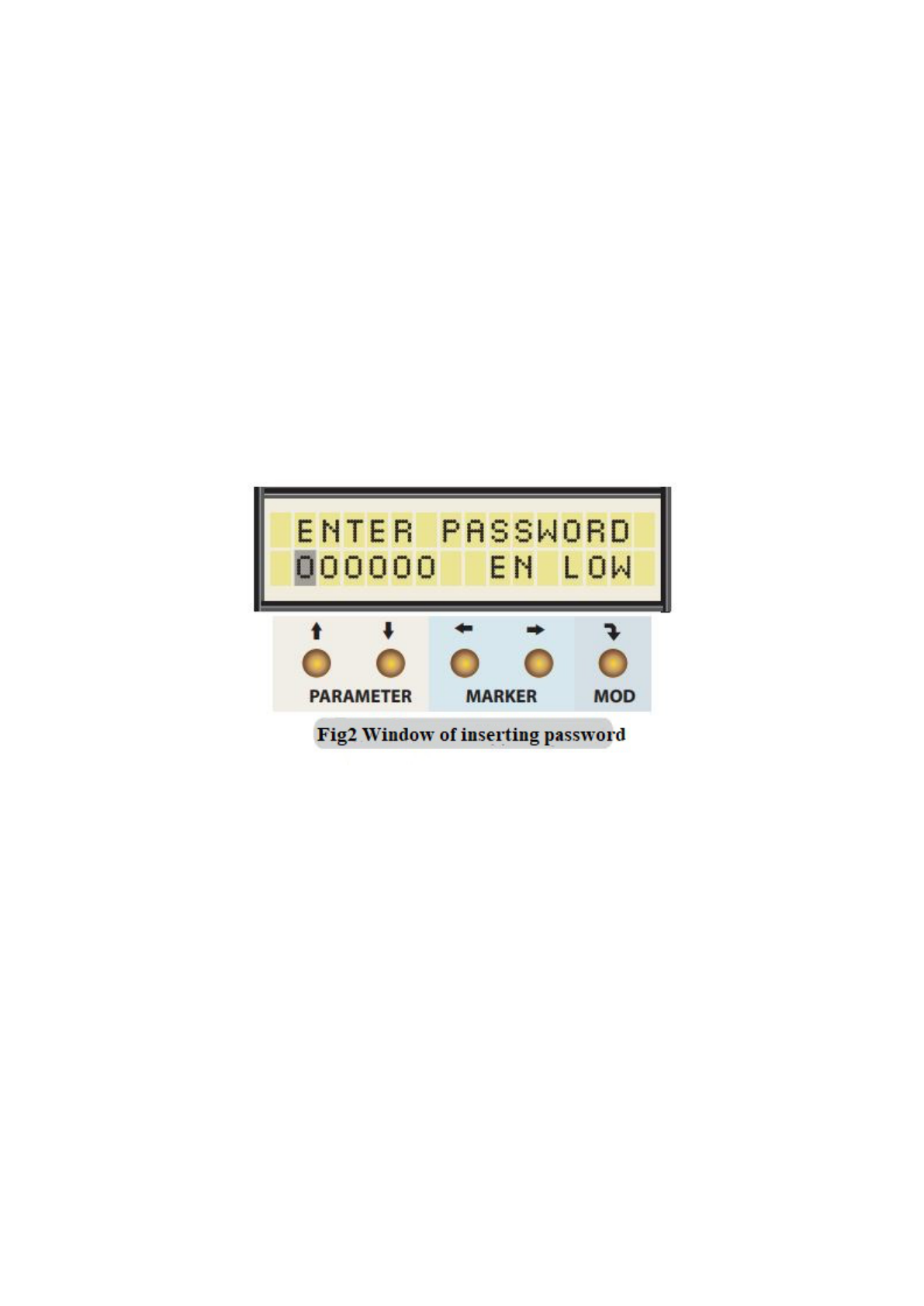
To start entering the password, you must press any of the buttons under the display to reset
greeting and switch the display to the password entry window (Fig. 2). This window has a field of
six zeros, which must be filled in with the password digits. On the right, there are two independent
switch password. EN / RU selects the instrument menu language, and LOW / PRO sets device
startup mode. LOW is an easy mode for general anglers with minimal the number of parameters.
PRO (PRO) - a mode with a full set of parameters for professionals and researchers.
Password digits are set using the buttons “MARKER”, which select a digit and “PARAMETER”,
by which its value is established. Likewise the password digit switches the menu language and
selects operating mode of the device.
When the password is typed, you must enter it by clicking onthe "MOD" button. If it's
wrong, for a few seconds the message “INCORRECT CODE!” will be displayed (Incorrect CODE
and the device will return to the password entry window. After 5 attempts to enter an incorrect
password, the device will be locked and will stop generating any messages. For prolongation
entering the password, you will need to restart the device (turn off the power for a few seconds and
connecting it again).
If the password is correct, the greeting “GOOD LUCK!” Will appear for a few seconds.
(Good luck!) And the instrument display switches to parameter display.
Attention! At the moment of entering the password, the “START” button must not be
pressed, otherwise the device will immediately turn on and supply high voltage to the landing net.
Therefore, in such a situation, the device will not start, and the display will show the message for a
couple of seconds: “DISSABLE THE START BUTTON! " (Disable the START button!). The
display will then return to the window. password entry. Disconnecting (pressing the contacts) the
"START" button, you need to re-enter the password by pressing the “MOD” button.
Instrument parameters
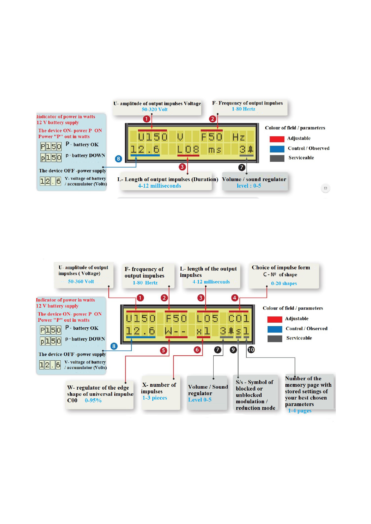
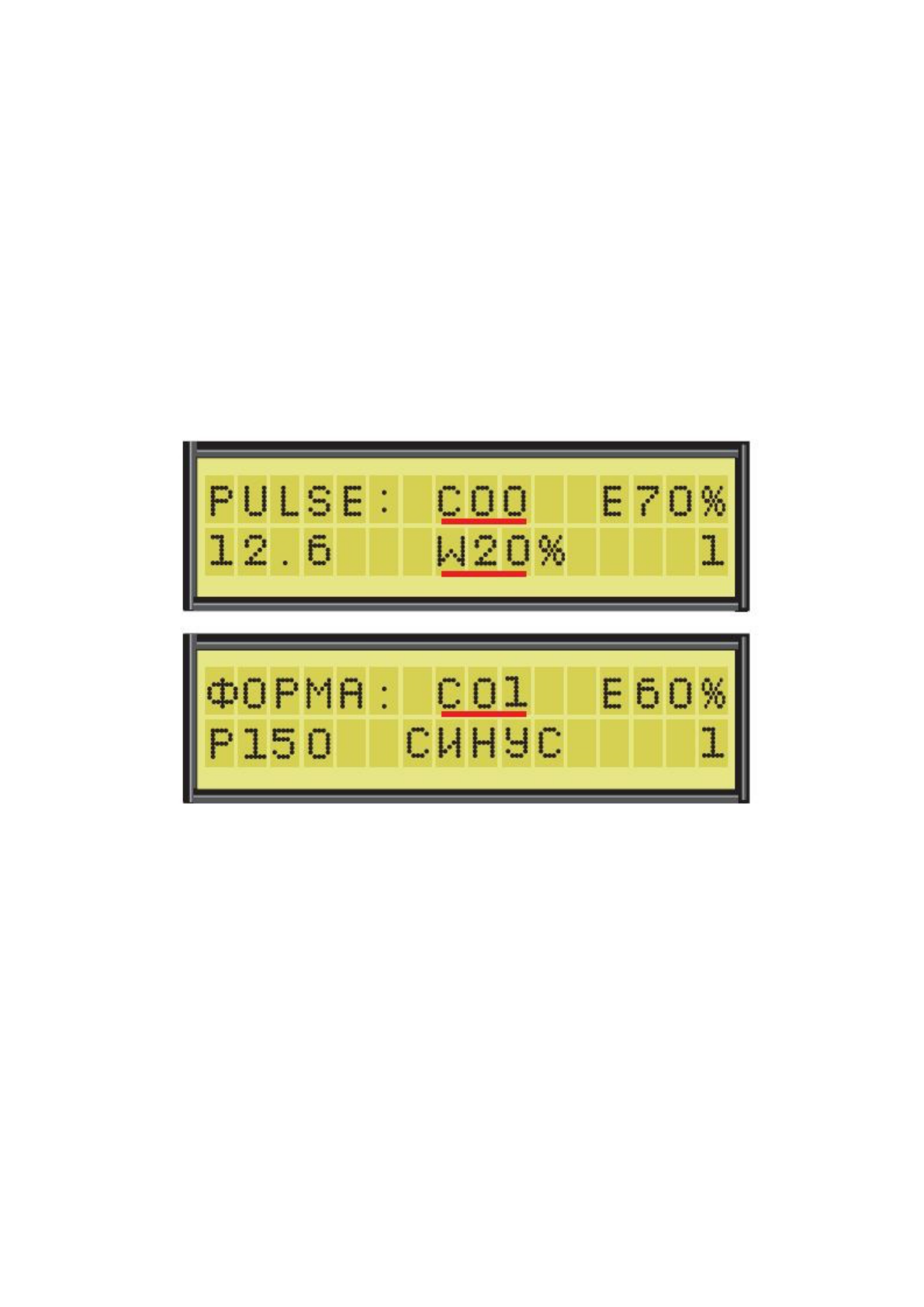
In LOW mode, only the most essential parameters are used (Fig. 3).
There are only 3 regulated ones plus two service ones, but this is completely enough for full-fledged
fishing and simple experiments. Due to the small amount, each parameters fit in one window,
which greatly simplifies the control of the device.
Fig. 3 LOW mode parameters window
In PRO mode, there is a complete set of parameters that can be controlled by 3 windows are used.
The main window (Fig. 4) contains all the main parameters, in the window "Pulse shapes" -
parameters for the selection of pulses and in the window "Reduction / modulation" - settings for
these modes. The last two windows will be described below in sections of the same name.
Fig. 4 Main window of PRO mode parameters
In both figures, the parameter types are distinguished by the color of the designation. The same
parameters in both modes are completely identical and are numbered. According to them below
a description will be provided for each parameter.

Main adjustable parameters
1) U - Amplitude / Voltage- maximum voltage in Volts at the high point of the pulse.
This is the most important parameter for the effect on fish. The amplitude depends on the
current strength in water during an impulse, which directly affects the receptors of the fish.
Additionally, the current depends on the conductivity of the water, the area of the
electrodes and the distance between them. In turn, the sensitivity of the receptors is different
depending on the temperature of the water and the state of fish, which is hardly susceptible
to impulses of weak current and is very critical of the strong. Thus, by tuning the amplitude
U to the best output fish, we ultimately achieve full matching of the device impulses with
the sensitivity fish receptors depending on all of the above factors.
Since amplitude and current directly affect the output power, optimal setting the
amplitude U automatically sets the required power level as well.
The amplitude U needs to be adjusted with an accuracy of plus or minus 5-10 Volts
from the required and adjust as fishing conditions change.
2) F - is the frequency of the output pulses in Hertz. Influences the muscle activity of fish and
is optimal when it coincides with the frequency of muscle contraction in fish or is a multiple
of it.
At an increased frequency, the fish is inactive, at a lower frequency, it is too mobile.
Usually set to a value of about 40-45 Hertz in winter and 50-55 Hertz in summer. In
winter, often drops to 30-20 Hz or in som mode up to 5 Hz. Particular precision and constant
adjustment of this parameter is not required. The frequency sets the number of pulses per
unit of time and thus also affects output power P.
3) L- is the duration of the output pulses in milliseconds. This parameter has no effect on
the strength of the current in the water, and sets the time of its effect on the receptors of the
fish. This directly affects to the output power. If the impulses are too short, the fish will not
be able to keep up to react to them, even if the U amplitude is maximum. In this way,
with the help of L, a certain initial power level at the output of the device is set,
which is later more accurately adjusted by the amplitude U.
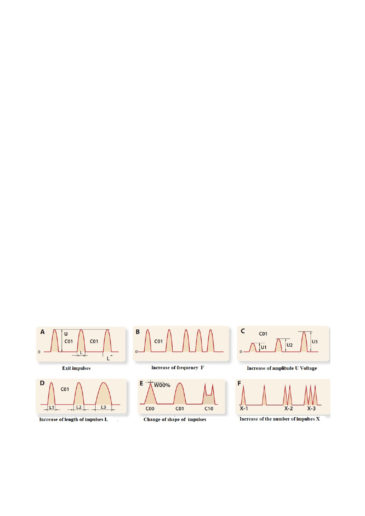
There is a second, more important effect of the duration L on the pulses. Its increase
slows down the rate of rise and fall of the pulse, and decreasing increases it.
This is shown in Figure 5D. This affects the matching of the slope of the pulse edges with
fast-acting fish receptors, especially in the hot summer period, when it
as active as possible.
In practice, at normal frequencies F (40-60 Hz), the duration L is set to 8 ms
and sometimes, depending on the reservoir, it decreases to 5 ms in summer. Change step
the duration is 1 ms and no special accuracy is required in its installation.
In the case of operation at low frequencies, the duration of L can be increased in order to
compensate for the decrease in power due to the decrease in frequency F.
4) C - pulse shape switch. Allows you to choose one of the 21 available in
the device of the forms of output pulses according to their serial number (C00 - C20). More
This knob is described in detail in the Pulse Shapes section below.
5) W - regulator of the top of the sawtooth pulse C00. Described in the section “Forms
impulses ”.
6) X - Number of pulses in burst mode. When operating at low frequencies, sometimes
it happens that the duration L is not enough to achieve the required output power P.
In such cases, you can activate burst mode by turning on pulse following not on
one (X1), as usual, but in packets of two (X2) or three (X3) pulses in a row.
This switch is not available at F frequencies above 25 Hz. It is displayed with a small
letter“X” and cannot be hovered over.
When the frequency drops to 25 Hz, a large “X” symbol appears and you can turn on
burst mode by setting 2 or 3 pulses. In this case, the previously set duration L is replaced
with a fixed value of 6 ms. When exiting batch mode, the previous the duration is
automatically restored. Exiting Batch Mode occurs when the frequency is set above 25 Hz
or when the X value is set to one pulse1.
7) Volume control . The number in front of the bell symbol specifies one of 5 sound emitter
volume levels. 0 is the muted state of the sound.
Controlled parameters
8) P - power / supply indicator is a combined parameter performing several functions.
When the device is turned off and there is no power, this indicator shows the value
supply voltage in Volts in the form, for example, 12.6 (This is 12.6 Volts). Its subsidence
below 10.5 volts indicates that the battery is unusable.
When the instrument is switched on, the indicator switches to the P symbol followed by
reading of the average measured output power in watts. If the voltage the battery under load
is normal, the P symbol is displayed with a capital letter, if lowers below 10.2 Volts, the
large letter changes to a small p, which is an indication discharged battery.
From the readings of the output power level, it can be seen whether the parameters of the
device are correctly set, how stable the conductivity of the water is, and even malfunctions
in the load cables.
By the state of the indication, it is possible to determine whether the device is on or off, as
well as serviceability of the control cable. For example, if there is no switching between
power supply and power P, which means that the device does not see signals from the
control cable.
Service parameters
9) s / S - Icon for blocking reduction / modulation modes. When displaying a small
with the letter “s” these modes and their window is locked. When switching to a large “S”
they are unlocked and turned on. Described below in the “Reduction / Modulation”
section.
10) - Pointer No. of parameter memory page. Described in detail below in the section
“Loading and saving parameters”.
At the end of the section, Fig. 5 are diagrams showing the appearance pulses, their
parameters and how they change during adjustments.
Fig. 5 Appearance and change of pulse parameters
Pulse shapes
The current in the water, acting on the fish, completely repeats the shape of the pulse.
In addition to the amplitude U and the duration L, fish receptors are very sensitive to the
rate of increase of the impulse, especially during the active summer period. The most effective
the effect is obtained when the impulse is coordinated with the speed of the receptors. The rules for
choosing the shape of the pulses are based on this principle.
In the “LOW / LOW” mode, there is no pulse shape regulator C and the default is sinusoidal
pulse C01, which works stably in all situations.
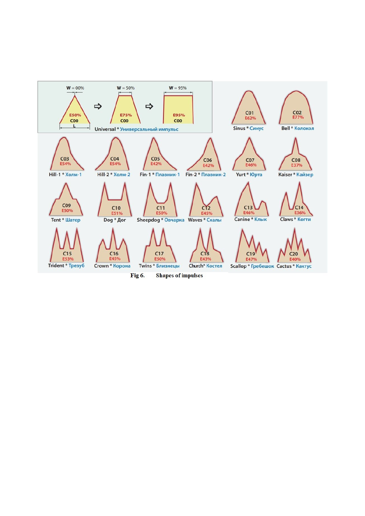
In PRO mode, the C knob can be set to any other pulse from tables (Fig. 6) by its serial
number. The impulses are matched with different rise and fall curves, symmetrical and not quite.
Starting from C10 they have several overshoots, which adds a spectrum of higher frequencies to the
output signal. This gives the effect of increasing the frequency without changing the main
parameter F and can facilitate fishing, for example, for pike in summer, when it is very playful and
likes an increased frequency, unlike all other fish species.
The figure shows the numbers and names of the pulses (EN / RU). Since the pulses differ in
shape and area, each of them will give a different output power.
To assess this before switching from one form to another, the relative power (energy) E of each
pulse is additionally shown in red in percentage with respect to a purely rectangular signal. The
higher the value of E, the greater the output power P. Thus, the pulse shape is the parameter that
affects the output power P.
After each change of the pulse shape, if the power P has changed by more than 10%, it may
need to be corrected with the amplitude U. Otherwise, the fishing efficiency may deteriorate and it
will not be clear why - from the new shape or because of the power change.
When you need to smoothly change the shape of the pulse and power, you can use the
universal pulse with the number C00. There is a parameter W for it, which regulates its shape by
changing the duration of the top in relation to the base. It can be seen from Fig. 6 that with an
increase in W, the pulse smoothly turns from a purely triangular to a trapezoid and then to an almost
rectangle. In this case, a whole variety of trapezoidal shapes are formed, the slope of the fronts
smoothly changes and the output power almost doubles. This parameter (W) is also available for
reduction / modulation modes.
The triangle signal has the shallowest edges and the lowest power. Its main area and energy
is concentrated in the base with a low amplitude, therefore it is the best
The triangle signal has the shallowest edges and the lowest power. Its main area and energy is
concentrated at the base with low amplitude, so it works best during the day in hot weather, but
unstable in cool water. Rectangular impulse C00 / W95% is the most powerful of them all, but also
ineffective due to very steep edges.
When the C00 pulse is not selected, the W parameter in the main window of the PRO mode
is unavailable; it shows dashes in its value field and the marker is not pointed at it.
The main window contains only the pulse number and this is inconvenient when you need to
frequently change or select a different pulse shape. Therefore, in PRO mode, additional window
“Pulse shapes” (Fig. 7), which contains more data on tabular pulses, which simplifies their
selection.
In the upper half of Fig. 7 shows a window view for universal impulse C00. In the center
there are C and W controls duplicated from the main window.
The power indicator and the switch of the parameter memory pages are also duplicated at the
bottom.
The top right shows the relative power of the selected pulse E (%) in percent.
In the lower half of Fig. 7 shows the window view for the rest of the table pulses using the
example of C01. At the bottom
instead of the W parameter, the name of the impulse is now written. Due to the duplication of
parameters, you can fish and shape the pulse right in this window.
At the end of the section, let us dispel fears that you can turn on any impulse and it will not
work. Any of them will fish, only with a difference of ± 10% efficiency between the most optimal
and “unsuccessful”. In addition, due to the smoothness of all forms, the imperfections of any pulse
can be easily corrected by adjusting the amplitude U.
Device control.
If you have successfully entered the password, then you already practically know how the
control takes place

parameters.
In the display windows, one of the parameters is always highlighted with a marker - black
blinking squares. Use the “Parameter” buttons to change the value of this parameter.
If the change has stopped, then it has reached the limit.
The choice of another parameter to the left / right - up / down is carried out along the ring by
shifting the marker by short pressing the “Marker” buttons. If the marker is not aimed at the
parameter position, it means that it is not available for adjustment.
In PRO mode, if you press the “Marker” buttons not shortly, but with a hold for more than
0.5 sec, you will switch between display windows.
It is possible to adjust the operating parameters and switch the display windows in any state
of the device - on (“on the fly”) or off.
Changing the parameter on the display when the device is turned on immediately takes
effect at the output.
The device is turned on when the “START” button is pressed and it emits pulses into the
water, accompanied by the blinking of the red “OUT” indicator and sound signals, and the power
indicator shows Watts after the symbol P.
The switched off device is not disconnected from the battery, but simply stopped by
opening the contacts of the “START” button. The device can be in this state for an unlimited time.
The "MOD" button, which was previously used to enter a password, now performs different
functions depending on the type of pressing or the duration of its holding.
A short press on the "MOD" button sequentially turns on and off the display backlight.
Other actions with this button are available only in the “PRO” mode when the device is off.
Pressing the “MOD” button for more than 0.5 sec switches
parameter memory pages (see the section “Loading and saving parameters” below).
Pressing and holding the “MOD” button for more than 8 seconds results in a reboot of the
device with a complete erasure of the entire parameter memory and installation of the initial factory
settings.
The usual reboot of the device or its complete shutdown is done by disconnecting the
supply voltage.
Setting up the device
Thanks to the use of HI-Width technology, the configuration of this model of the device has
been greatly simplified. But the first fishing with this device for beginners
users are advised to start by running it in “LOW” mode.
After entering the password for the first time in any of the modes, the initial factory
parameters are loaded. This is the average optimal frequency F = 50 Hertz (for the spring-summer
mode), a low amplitude U = 150 Volts, since the conductivity of water is not yet known, as well as
an increased duration L = 8.0 ms for setting the optimal slope of the fronts. The pulse is set to
sinusoidal C01, burst mode (X1) and reduction / modulation are disabled.
These parameters are perfect for starting fishing. If it's not hot already, you can lower the F
frequency to 45 Hertz.
Now it remains to choose the amplitude U, at which the output and retention of the fish will
be the best. To do this, you need to start fishing.
An equipped boat with a connected device and a sheath lowered into the water must move
away from the shore to its original position. It is advisable to choose a shallow (up to 1.5 m) place
with aquatic vegetation, bushes, snags and other shelters, where fish live and
feeds. At this depth, the fish will be clearly visible and this will greatly facilitate the setup.
Smoothly raising the amplitude U, we achieve the exit of the fish. Raising U even higher, we
achieve that the output becomes clear, and the retention of the fish is confident. You need to
increase U until the fish is heated. Thus, the upper threshold of the sensitivity of fish receptors is
found. Stepping back a little, you can finish the setting.

It is possible that at the first start-ups, the fish will immediately begin to heat up. Above 100
watts, this will be due to contaminated water. At low power levels, this can be in shallow waters, or
when the fish is simply weak. In both cases, feel free to lower the U amplitude down to a minimum
until the fish output stabilizes.
When adjusting the amplitude U, control the output power P. It should not go up far beyond
200-250 watts, otherwise the U setting is not done correctly. In standard ordinary reservoirs, at the
end of the device setup, the working amplitude U should be 180 - 250 Volts, and the power P up to
130 W in winter and up to 160-200 W in summer.
Excessive amplitude (power) leads to sharp splashes of fish on the sides of the boat and the
release of a small amount of it deep under the landing net almost above the very bottom.
If the amplitude is below normal, the fish comes out uncertainly, does not stop at the landing
net ring, and often leaves the area of the device's operation at will.
When the amplitude is tuned and the fish is being caught, you can, if desired, fine-tune some
of the other parameters. If the fish flies too quickly to the landing net and does not have time to stop
nearby, you should reduce its mobility by raising the F frequency by 3-5 Hertz or higher. If the
output is sluggish or the fish is inhibited by dense vegetation, its mobility can be increased by
lowering the frequency by 3-5 Hz or more.
You can also try shifting the length L down. Then the optimal amplitude U will change in
the opposite direction. This can improve the fishing efficiency.
the following rules when adjusting the device parameters.
Lower the landing net into the water completely with the entire ring. It is a component
of the total area of the electrodes, on which the current strength in water depends. Incomplete
sinking will reduce area and current, which will reduce power and make fishing unstable.
Do not immerse the ring deep in water. Fish emerge most often under it and within a
radius of a couple of meters around. In this case, it will not be visible how this happens.
It is useless to adjust the parameters while standing in one place. Having felt the field of
the device, the fish will scatter to the sides in the first seconds if the parameters are not optimal. Or,
having received the first influence from the parameters, the fish will no longer react normally to
their change. Therefore, having completed one turn on, you should turn off the device and move to
a new place, which should be no closer than 10 meters from the previous one.
The duration of pressing the "START" button depends on the time the fish emerges and the
depth of the reservoir and usually does not exceed 10-15 seconds. If the fish output stops earlier, the
start time can be shortened.
Change the parameters smoothly and only one at a time. If you change several
parameters at the same time, you will not know which of them and how affected the fish. In this
case, the logic in the configuration may be lost and an extremely ineffective setting of parameters at
random will turn out.
If the parameter is changed immediately by a large value, it is possible to overshoot the
optimum setting point, which can also confuse the device adjustment.
After changing the parameter, it is necessary to make not one inclusion, but several in a row
in different places in order to exclude random factors affecting the output of fish.
It could be located across the field of the device or away from the lines of force and, because of this,
it could not come out as it should. Only after obtaining a clear picture of the output can you make
further changes to the parameter.
If there is no fish coming out, do not change the parameters until it appears. The fish is
unevenly distributed in the reservoir and in this place it simply may not be there, and you, thinking
that the set parameters do not work, in vain shift them to the side. What if at that moment they were
the most successful? The fish is visible at almost any, even completely non-optimal, parameters, so
you don't have to worry that you will miss it.
Do not adjust the instrument based on the behavior of the fry. The impact on it can be
quite different (very weak) than on large fish. Look at the exit of fish only from 100 grams and

above and adjust the required amplitude U according to it.
Don't turn up the power to “kick well” the fish. In this case, she will scatter, hit the
bottom or anywhere, but not go up. The best fish yield from the maximum distance and depth
occurs with the minimum possible amplitude and power!
Catching fish
Catching fish consists in moving the boat across the reservoir, periodically turning on the
device and collecting fish with a landing net. The efficiency of fishing depends on the knowledge of
the reservoir and the fish habitat in it, since it is not always distributed evenly in it and not
necessarily in those places that, in the opinion of the fisherman, seem promising.
You should be aware that before a significant change in weather, fishing efficiency drops
noticeably. She can feel it in 20 hours. The fish becomes much smaller, it begins to behave
nervously and come out unstable. There are many departures. No adjustments help to improve the
yield, whereas in stable weather it comes out stably at almost any setting.
Fishing also worsens in summer in the heat. During this period, fish have an increased
sensitivity of receptors and a reduced percentage of oxygen in the water. In this case, the use of the
smoothest impulses and a more accurate setting of the rest are required.
In the cold season, fish are not so sensitive to settings and therefore easier to catch.
Fishing at night, especially predatory, is much more effective. She comes closer to the shore from
the depths and is not so afraid of an approaching boat as during the day. The light of the lantern
does not frighten her either.
Unstable fish output can occur when fishing at a depth of more than 2 m. This requires some
experience from the angler.
Having achieved good results in one body of water, when switching to another, you may
need to adjust the parameters differently due to the difference in the conductivity of the water and
the state of the fish.
Check the supply voltage more often during operation. If, when the device is turned off, it
sags below 11 Volts, then it will be much lower when it is turned on under load. When the small
letter "p" is highlighted, this is already a signal that the device's drivers may turn off at any moment
and with such a power supply it will completely stop fishing.
Be observant, study and memorize the habits of the fish and the successful combinations of
the parameters of the device. Experienced anglers catch fish much easier and more than ordinary
anglers.
Try to take the time to experiment with the parameters to find your own custom settings and
modes. There is a chance that you will get lucky and your work efficiency will increase.
Reduction / modulation
During the operation of the device, the set parameters are constant. But there are situations
when it is necessary for any of them to automatically change in time by a given amount and at a
certain speed. In this model in the "PRO" mode there is a means for this - the modes of reduction
and modulation.
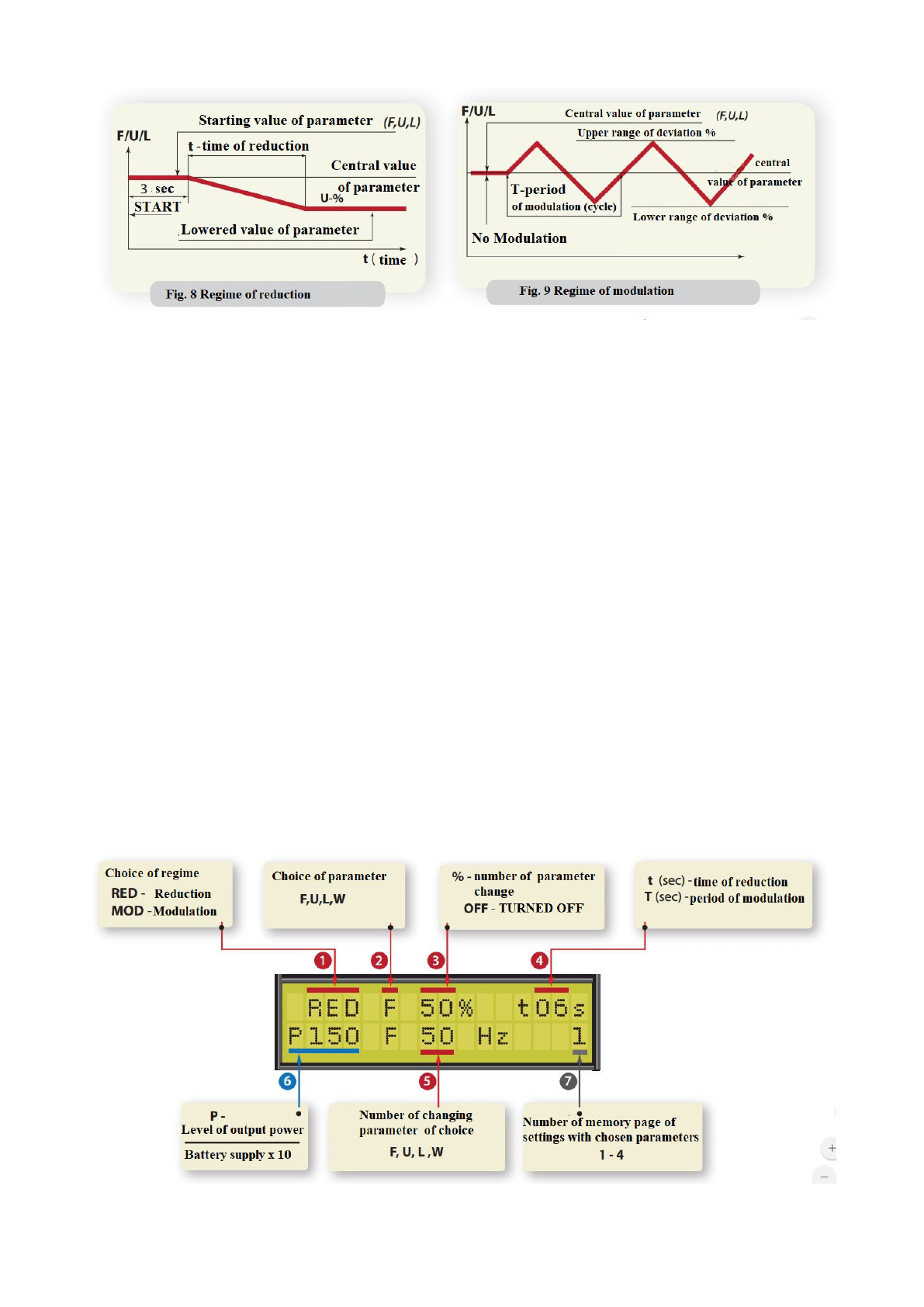
Reduction is an automatic one-time reduction of a parameter by a specified number of
percent during a specified time interval t (Fig. 8).
The idea of the reduction is that after turning on the device for the first 3 seconds the impulses act
on the fish in full force (according to the set parameters) and force it to move towards the landing
net. But, as the fish approaches the ring, where the electric field is stronger, the selected parameter,
and, consequently, the output power level, begins to decrease, weakening the field and making it
easier for the fish to move upward. This saves battery energy and minimizes the effect of the
device's field on fish.
Modulation is an automatic constant and linear change of the selected parameter in time up and
down by a specified number of percent over a specified period of time T (Fig. 9). Simultaneously
with the change in the parameter, there is also a change in the output power P.
By constantly changing the desired parameter within certain limits, modulation often helps,
at least briefly, to capture the optimal tuning points and improve instrument performance.
During reduction / modulation, only one of the main adjustable parameters can be changed:
frequency F, amplitude U, duration L or duration of the top of the universal pulse W, if this C00
pulse is selected in the menu.
Setting up and enabling the reduction or modulation modes is done in the reduction /
modulation window (Fig. 10).
In order not to confuse ordinary users with unnecessary parameters and to exclude the
inclusion of these modes after connecting the device, the reduction / modulation window and all
parameters previously set in it are initially locked (disabled).
The lock is removed in the main parameter window by toggling the reduction / modulation
window lock icon [pos. 9] from a small letter “s” to a large “S”.
The transition to this window and return from it is made by successive pressing and holding
any of the “MARKER” buttons.

Further, to use these modes, you must:
1. In position [1] select the reduction mode “RED” or modulation “MOD”.
2. In position [2] select the parameter to be changed.
3. In position [3] set the number of percent by which the value of the selected parameter will be
changed.
4. In position [4] set the reduction time “t” for “RED” ”or the modulation period“ T ”for
"MOD". Both times are shown in seconds. For reduction, this is the immediate descent time from 3
to 12 seconds, and for modulation, it is the time during which it completes one cycle. It is set from 3
to 15 seconds.
Position [5] shows the current value of the parameter selected to change.
If you hover a marker over it, it will become available for adjustment (without switching to
the main window).
For the convenience of setting the reduction / modulation modes, the output power indicator
P [6] and the number of the parameter memory page [7] are duplicated in the lower line of the
display from the main window.
Parameter selection, percentage and time (period) are set individually for reduction and
modulation.
If the percentage of the parameter change is 00%, the zero change of the parameter will
mean the off state of the mode and the message “OFF” will be displayed in this place.
You can also turn off these modes in the main parameters window by switching the lock
icon to the small letter “s”.
For the convenience of controlling the central value of the changed parameters and the
power level, when the reduction or modulation is on, changing any of the device parameters using
the “PARAMETER” buttons will turn off the reduction / modulation action for 3 seconds, and then
start them again.
The reduction time “t” is selected based on the depth of the reservoir and the speed of fish
emergence.
If during normal fishing the fish goes to the landing net on average 5-7 seconds, then the
first 3 seconds should be taken into account. pauses before switching on the reduction plus the time
of the reduction itself. For our case, the optimal value is 6 - 9 sec. (t06s - t09s). Special precision is
not required here.
Amplitude reduction (RED U 30-40% t06s or t09s) can simulate a connected battery.
Reducing the modulation of the duration L affects only the level of output power, amplitude U or
frequency F - on the power and on the behavior of the fish. The frequency has a greater effect on
mobility, and the amplitude - on the power and depth of fish emergence.
The reduction / modulation modes are recommended to be used by more experienced users
who are well aware of which parameter and how it affects the fish yield. Before turning on these
modes, it is recommended to first fish with constant parameters in order to know exactly which of
them and by what percentage should be changed.
Start using these modes with small percentages (no more than 10-20% for modulation and
30-40% for reduction). Later, the optimal percentage is selected in the process of fishing for the
best fish yield.
There are some limitations to consider when using these modes.
Modulating a parameter with zero or very little value will give zero change. If the parameter is set
close to the limit of the range, the modulation will turn out to be unbalanced, since the parameter
cannot go beyond this range. When using modulation of frequency F in catfish mode with
parameter X-2 or X-3, it will not rise above the value of F25 Hz from above.
The most optimal modulation periods are slow and medium modes T06s - T10s (from 6 to
10 seconds), as they are well tested in practice. Faster modulation affects fish more difficult and we
are asked to include it in the menu mainly by scientists and experimental anglers.
Using reduction / modulation modes at very low percentages of parameter change will have

almost no effect on fish output. Optimal selection of mode, parameter, percentage and time (period)
can improve fish yield. Use of these modes by inexperienced users with incorrect settings can lead
to loss of fishing efficiency.
At the end of the section, an example of setting the modulation of the U250V amplitude to
30% with a period of T10 sec is given by calculating the required percentage of deviation.
After 3 sec. after turning on the device, the amplitude will start vary from 250 Volts within the
following limits:
Up 250 x 1.30 (%) = 325 Volts Down 250 / 1.30 (%) = 192 Volts
Loading and saving parameters
During fishing in both modes, all adjustable parameters are automatically saved in the
device's memory, so that when connected next time, the last parameters with which the previous
fishing was completed will be loaded.
In “LOW” mode only the current set of parameters is saved, and in “PRO” mode it is
possible to store 4 sets in 4 memory pages. The loaded page number is displayed in position [10]
fig. 4 main parameter windows.
When connecting the device, memory page # 1 is always loaded. Further, you can
successively go to pages 2-3-4. Thus, in the process of fishing, when, due to changes in fishing
conditions, it is necessary to often rebuild the device, there is no need to memorize the values of the
successful parameters in your head and then manually return to them again. The entire set of
parameters can be saved on the current page by switching to the next one, where you can re-select
other parameters and then quickly switch between pages.
Switching is available only when the device is off and is performed by pressing the MOD
button for 0.5 sec. From the last page no. 4, the switching will occur along the ring again to page
no. 1.
You can change the parameters for a long time and fish. But they will be overwritten into the
internal memory only at the moment the device is turned off or in the off state when
go to the next page.
If the parameter memory is full of unnecessary parameters, it can be completely cleared by
pressing the MOD button for about 8 seconds until the device is restarted and all pages of the
parameter memory are cleared. In this case, you will have to re-enter the password to activate the
device.
Catfish regime / mode (Rivers only and access to rivers lagoons )
Above, we considered the settings of the device and fishing in the usual mode, when all
types of fish are almost equally caught, but in a limited radius and depth and at an increased
frequency F and power.
If the frequency F is lowered down to 6-8 Hz, in summer the device will start catching
catfish from great depths and within a radius of up to 40 meters at a power P from units to several
tens of watts. This regime is called catfish. A boat with a continuously switched on device should
move slowly over the channel, pits and places where catfish may be found. Once in the range of the
device's field, they start almost immediately or with
a small delay with noise and burst to go upstairs.
The catfish mode is activated automatically if the frequency F is set to 25 Hz or less.
The only difference in this mode is that the device starts to turn on and off by one short press on this
button. This is done in order not to keep the “START” button constantly pressed for a long time.
Parameter setting in catfish mode is done as usual. L and C are installed with subsequent
power regulation due to the U amplitude, focusing on a good yield of catfish. But the frequency F is
adjusted quite accurately in order to achieve a confident retention of catfish on the surface of the
water after leaving.
The amplitude U can be obtained even at a level of 100 Volts and below - this is a normal
value, since soms need very little power.
The efficient use of the modulation mode can increase the efficiency of catfish fishing.
Frequently the frequency F is modulated here.
In cold weather, catfish fishing practically stops and slightly resumes with the onset of
winter, but already at a frequency of 10-12 Hz and a power of about 100 watts. But such fishing is
usually impossible because of the ice. If it is not there, then fish is still caught unstably due to the
strong dependence on the weather and uneven distribution in the reservoir. Catfish did not always
hibernate in the pits due to water pollution, especially with phosphates.
In the cold season, from October to March, when the fish is sluggish, the catfish mode can
be used as a deep one if the frequency F is raised to 18-20 Hz, and the power P due to the
amplitude U to 100-120 watts. At the same time, almost all species of fish will rise from deep
places with a delay depending on the depth and condition of the fish. All this time, the boat with a
continuously switched on device must constantly be above the location of the fish. It should be
borne in mind that this mode also depends on the weather and many other factors and does not
always work, especially in reservoirs with stagnant water.
Catfish and deep modes require the experience and qualifications of the angler and are rarely
immediately obtained from beginners.
Device protection
This device is equipped with protection against overcurrent and power, from operation without load
at idle and from exceeding the supply voltage over 13 volts.
Overcurrent protection is triggered if the current consumption by the device exceeds 45-50
Amperes. In this case, the device is turned off and blocked, and the display shows the message
shown in the figure on the left. The blocking lasts about 8 seconds and is accompanied by sound
signals. At the end of the blocking time, the black squares disappear and the display returns to the
main parameter window.
The reason for the operation of this protection may be the setting of deliberately
overestimated parameters, critically low water resistance, a short circuit of the electrodes in the
water, or even a device malfunction. In case of repeated trips of this protection, the output power
should be reduced by U and (or) L.
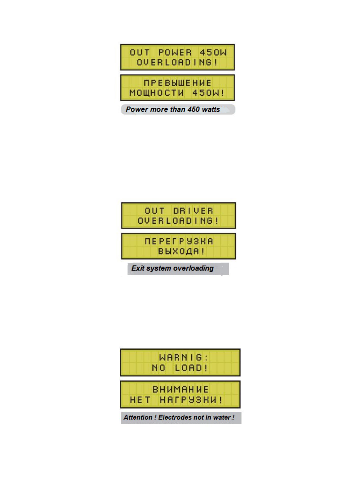
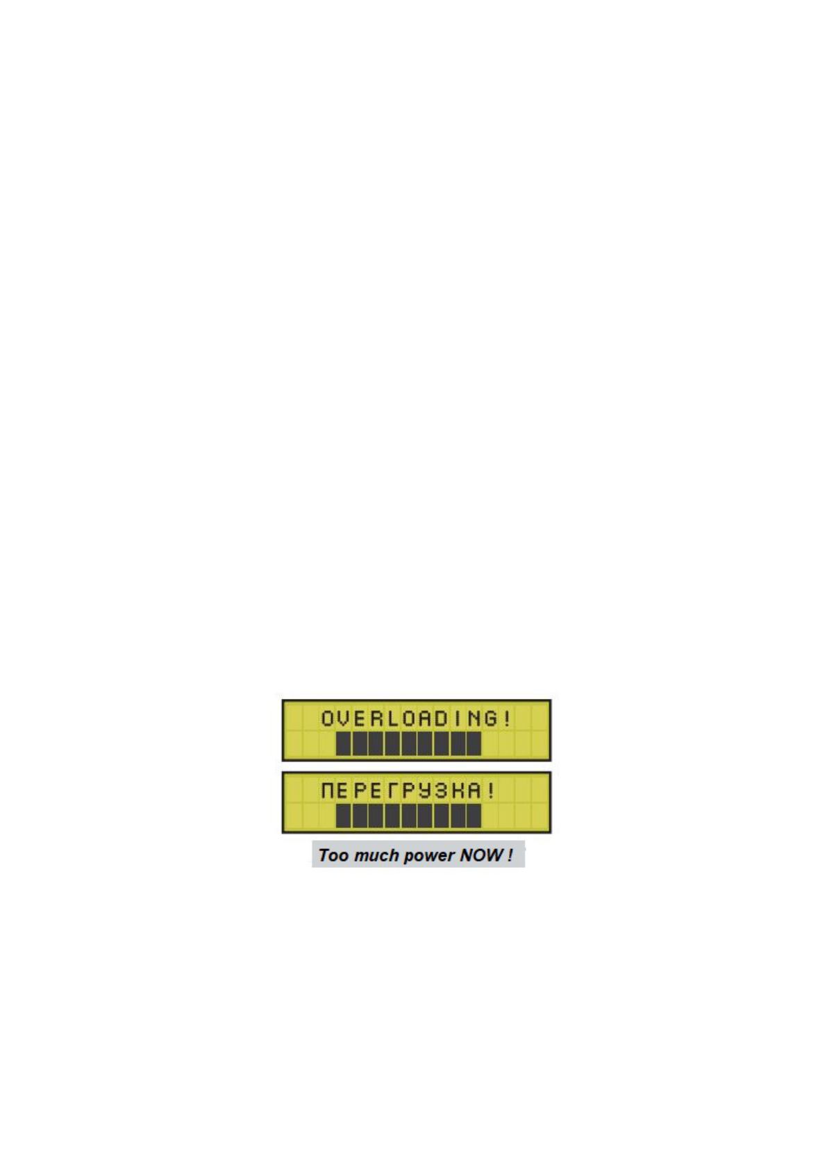
In order to increase reliability and take into account environmental requirements, the device
has an additional software power limitation at the level of 450 watts. When
exceeding this power, the device will turn off and display a message according to the figure on the
left.
After a few seconds, the overload message will disappear and the device will return to
working condition. In case of repeated tripping of this protection, it is necessary to manually reduce
the output power level of the device.
Output overload protection is activated in case of exceeding the pulse current of the output stage
over 20 Amperes. In this case, the displayed message will be displayed for a few seconds and then
the device will return to working condition. The reason for the operation of this protection is an
extremely low water resistance (below 15 Ohm) and (or) an overestimated U amplitude in case of
contaminated water. You should try to reduce amplitude U.
No load is an idle protection message, which is triggered if the load is lost (output power
drops below 6 watts). This situation is harmful to the device circuitry and dangerous to the user. For
example, if a landing net with a fish rises from the water, and the START button is not turned off

due to inattention.
In this case, the instrument turns off with the displayed message. After a few seconds, the
device will return to the working window of parameters and can be switched on again.
The reason for the operation of this protection may be non-contacts or breaks in the load
cables, or when they simply forgot to lower the braid into the water.
Over-power protection prevents the device from turning on if it exceeds 13 Volts. It was
introduced due to the occurrence of instrument failures during power supply from generators of
outboard motors or boats. This power supply can be from 14 to 15 volts, which is much more than
acceptable.
If this lock is triggered, the displayed message appears for a few seconds.
The operation of overload protections is an emergency situation for the device circuit,
therefore, they cannot be caused deliberately, for example, by shorting the output cables or
terminals of the device, and also deliberately raise the output power above the limit.
Precautionary measures
The following precautions must be observed in order for the device to serve for a long time
and work safely.
The device is a source of high voltage! Therefore, do not turn it on near bathers, do not
lower your hands or feet into the water, and do not touch the bare parts of the landing net and the
sheath while the “START” button is pressed.
Insulate the handles of the landing net and oars if they are metal.
Keep the instrument in a boat in a dry and elevated place to avoid water getting into the
body of the instrument or itself into the water. If this happens, immediately disconnect the device
from the battery and take it to a dry, warm room. Then immediately unscrew the 4 screws in the
case (in plastic washers), separate the upper case cover and dry the device thoroughly for several
days. Do not do this near heating devices or around a fire. Turning on a wet device can immediately
disable it.
After finishing fishing, be sure to store the device in a dry, heated room in winter. After
intensive fishing in rainy weather, it is also useful to sometimes unscrew and remove the top case
cover, leaving the device in this position for several hours so that the residual moisture
condensation evaporates from the inside.
Do not block the air access to the radiator for its natural cooling. When operating intensively
at higher power levels in warm or hot weather, it may become warm.
Do not place an operating device in tight covers or keep it in a boat in direct sunlight.
The higher the output power of the device and the longer the “START” button holding
time, the longer the pause between switching on should be, so that the radiator and power elements
of the circuit have time to cool down. Usually such a pause is obtained automatically, while from
the landing net the fish is unloaded and the boat moves to the next position.

For safe operation of the instrument, do not make electrical contact between low voltage 12-
volt power circuits and high-voltage output circuits. Low voltage circuits are battery power cables
and control cable pins. High voltage output circuits are load cables, landing net and water through
which the output current flows.
Such contacts can arise due to moisture or water in the device case, due to a backlight lamp
on a landing net with a base poorly insulated from water, when it is powered from the same battery
with the device. There may also be violations of the external insulation of the power and load cables
located nearby.
Do not power the device from the on-board network of boats and generators of outboard
motors, since their operating voltage exceeds 14 volts! The common wire of such floating craft is
connected to the body and is in the water, where the high-voltage voltage of the device is
simultaneously present. This can damage not so much the instrument itself as it can damage the
boat's expensive electronic equipment.
If it becomes necessary to check the operability of the device at home, the device can only
be connected to a 12 Volt battery, but in no case to chargers or homemade rectifiers, which, at low
load, can produce voltages above 20 Volts.
It is strictly forbidden to check for the presence of “spark” output pulses by shorting the
output terminals. In this case, as a load, you can use a bucket of water or an ordinary old
incandescent lamp for 220 volts 50 hertz with a power of 100-200 watts. But at the same time, it is
necessary to lower the amplitude U to 150 Volts or lower so that the spiral of a cold light bulb,
having a resistance below 10 ohms, does not overload the output.
During the operation of the device, monitor the condition of the power and load cables.
Insulation abrasions can lead to current leaks, and internal breaks in the wires in places of frequent
bends disrupt the flow of current, which can lead to a violation of electrical safety or to the loss of
the device's performance.
If damage is found, replace the wires in the cables with new ones of the same cross-section
or larger than those included in the kit (1 - 1.5 mm²).
Observe the state of the contacts of the “START” button so that no water gets under the
rubber waterproof cap, otherwise the device may be turned on all the time. In the case of replacing
the microswitch, it should be assumed that to turn on the device, its contacts must close, and the
voltage across them is a couple of volts at a current of several milliamps.
Do not apply any extraneous voltages to the contacts of the “START” socket, lay high-
voltage load wires next to them.
Avoid shock and excessive mechanical force on the controls of the device.
To prevent the output terminals from breaking from the frequent attachment of thick wires,
use special single plugs that are inserted into the terminal overhead as in a power outlet. They are
cheap and sold at every radio store.
Possible problems
During the operation of the device, users, especially beginners, sometimes have problems. Most
often they are insignificant and are associated with non-contacts, errors in connection and
management, or incorrect parameters. To quickly identify this cause and correct it on the spot,
below is a table of typical problems.

Problem
Signs
Reason / Solution
Password not entered
when the button is pressed
"MOD"
The message is displayed:
Disable the START button
DISSAВLE THE START
BUTTON /
Nothing happens
Wrong password entered
The START button has been
pressed. Squeeze it out.
1. The device is locked after 5
attempts entering an incorrect
password. Restart it.
2. The "MOD" button does
not work
Check: Disconnect the device
from 12V and
in a couple of seconds.
reconnect. Reset
cap by pressing the "MOD"
button. If nothing
does not happen - the button
does not work.
The device does not turn on
from the START button
At the moment of pressing, the
power indicator P continues
show supply voltage
The message is displayed
WARNING: NO LOAD! /
No load
Overcurrent protection is
activated
The message is displayed:
OVERLOADING! /Overload
IIIIIIIIIIIIIIII
Protection is triggered
from exceeding the power
above 450 watts
The message is displayed:
OUT POWER W
OVERLOADING! /
Excess power 450 watts
The message is displayed:
No contact closure kn.
"START" or
open circuit in the control cable.
Try to short-circuit something
manually
two pins of the “START”
socket
Breakage or non-contact in load
cables
or landing net
If you disconnect the load and
the overload disappears:
1. Deliberately overestimated
parameters have been set.
2. Critically low water
resistance.
If the overload persists: device
malfunction or water in the
device case.
Overestimated parameters are
set
F, U, L or W
Reduce any of them

OUT DRIVER
OVERLOADING! /
Output overload
(Output stage protection is
activated
from excess current through it)
The device restarts:
2 beeps appear and
welcome window
1. Very low water resistance.
Try to turn it on without a
landing net in the water.
2. Overestimated amplitude U.
Try to reduce it.
Power and battery cables are
loose.
Discharged or unusable battery.
Short circuit in the device
circuits when turned on
The device does not "hold"
the parameters
Floats up and down power P
The power indicator symbol
switches to the small letter “p”
The parameters on the display
change spontaneously.
1. The mode of reduction or
modulation is on
2. Inconsistent water resistance.
In water a lot of unmixed
impurities (salts) - somewhere
nearby wastes dumping into
water.
3. Poor contact of the wire with
the landing net.
Discharged battery or
bad contact
Any of the "PARAMETER"
buttons closes
Perhaps the parameters are
automatically reduced due to
the operation of the overcurrent
protection or the reduction /
modulation is on.
Warranty obligations
The warranty period for the device is 3 years from the date of sale. We guarantee free repair
or replacement of the device, provided that the user has followed our recommendations for its use.
Our warranty obligations do not apply to devices with obvious mechanical damage to the
case, which are out of order as a result of water entering the case, or have undergone unauthorized
modernization, circuit change or improper repairs. In this case, paid repairs will be made on a
general basis.
In case of problems, please contact our dealer where you purchased the device.
If this is not possible, if repair is necessary, you can contact your nearest electronics
engineer or qualified one of our repairman team.

Table of contents
Device characteristics. . . . . . . . . . . . . . . . . . . . . . . . . . . . . 1
Completeness of the device. . . . . . . . . . . . . . . . . . . . . . . . 1
Connection and control bodies . . . . . . . . . . . . . . . . . . . . . 2
Password input. . . . . . . . . . . . . . . . . . . . . . . . . . . . . . . . . . 3
Instrument parameters . . . . . . . . . . . . . . . . . . . . . . . . . . . 3
Pulse shapes . . . . . . . . . . . . . . . . . . . . . . . . . . . . . . . . . . . . 6
Device control. . . . . . . . . . . . . . . . . . . . . . . . . . . . . . . . . . . . 8
Reduction / modulation . . . . . . . . . . . . . . . . . . . . . . . . . . . 10
Catching fish . . . . . . . . . . . . . . . . . . . . . . . . . . . . . . . . . . . .11
Setting up the device . . . . . . . . . . . . . . . . . . . . . . . . . . . . .. 12
Loading and saving parameters. . . . . . . . . . . . . . . . . . . . .14
Catfishing mode . . . . . . . . . . . . . . . . . . . . . . . . . . . . . . . . 14
Device protection . . . . . . . . . . . . . . . . . . . . . . . . . . . . . . . 15
Precautionary measures . . . . . . . . . . . . . . . . . . . . . . . . . 16
Possible problems........ . . . . . . . . . . . . . . . . . . . . . . . . . . 17
www.electro-fisher.com email : electrofishers@gmail.com
All copyrights reserved to constructor and inventor ---Alexander Samus !
